Doepfer
Doepfer New A-100 Slim Line Series Eurorack Modules
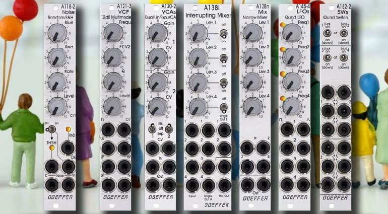
Doepfer has now launched its new range of new Slim Line Series modules. These new modules have been presented at Superbooth 2019.
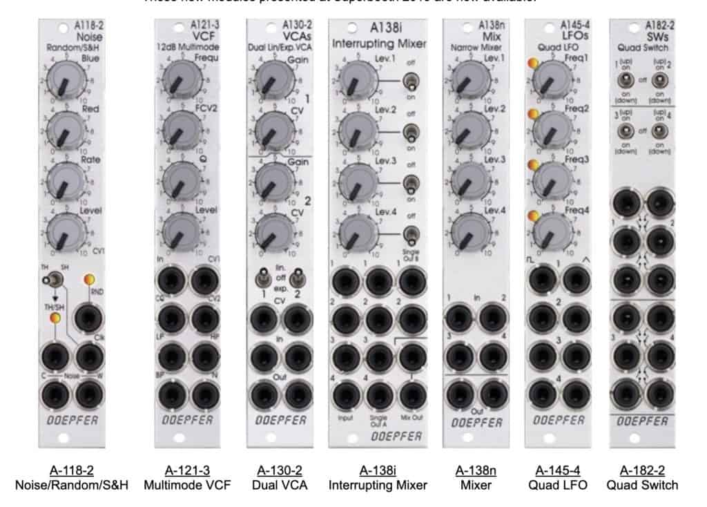
Available Slim Line Series Modules
- Doepfer A-118-2 Noise / Random / Track and Hold / Sample and Hold
- Doepfer A-121-3 Multimode Filter / VCF
- Doepfer A-130-2 Dual linear/exponential VCA
- Doepfer A-138n Narrow Mixer
- Doepfer A-138i Interrupting Mixer
- Doepfer A-145-4 Quad Low-Frequency Oscillator LFO
- Doepfer A-182-2 Quad Switches
Doepfer launched the first collection of Slim Line Series modules and there are more to come like the A-111-6 Miniature Synthesizer.
Doepfer A-118-2 Noise / Random / Track and Hold / Sample and Hold

Doepfer’s A-118-2 Noise / Random / Track and Hold / Sample and Hold generates the signals white noise, colored noise, continuous random voltage and stepped random voltage. The noise signal is generated 100% analog by amplification of the noise of a transistor. White and colored noise are usually used as audio sources. The random voltages are normally used as control voltages (e.g. for filter frequency or any other voltage controlled parameter).
The A-118-2 gives you the ability to mix the relative amounts of Red and Blue noise (low/high-frequency component) in the colored noise output. For the continuous random voltage, the rate of change (Rate) and amplitude (Level) of the random voltage can be adjusted. The continuous random voltage is used as a source for the S&H/T&H unit. The type of operation can be set to S&H (sample and hold) or T&H (track and hold). When T&H is chosen the output signal follows the input signal as long as the Clock input is “high”. As soon as the clock signal changes to “low” the last voltage is stored.
When S&H is chosen the input signal is sampled at the rising edge of the Clock signal. For the Clock signal, a “digital” signal (e.g. Clock, Gate, rectangle output of an LFO) is required. Dual color LEDs are used to indicates the continuous and stepped random voltages.
Doepfer A-121-3 Multimode Filter / VCF

Doepfer’s A-121-3 Multimode Filter is functionally nearly identical to module A-121-2. Only the distances between the controls and sockets are smaller and rubberized, small rotary knobs are used. Therefore the front panel width is only 4HP compared to 8HP of the A-121-2. In the first place, it is planned for applications where only limited space is available. The only functional difference compared to the A121-2 is the missing attenuator for the resonance CV input CQ.
- Voltage-controlled multi-mode filter with a cut-off slope of -12 dB / octave (identical to the filter of the Dark Energy II/III but has been expanded by the voltage controlled resonance feature)
- Four simultaneous outputs are available, each with different characteristics: low-pass (LP), high-pass (HP), band-pass (BP) and notch (N)
- Manual control Frequ. for the cut-off frequency of the filter (the cut-off frequency determines the point at which the respective filter effect appears)
- Two inputs for frequency control by means of external control voltages (frequency modulation, e.g. by ADSR or LFO)
- Control voltage input CV1 without attenuator, about 1V/octave sensitivity
- Control voltage input CV2 with attenuator FCV2 for the adjustment of the modulation depth of input CV2
- Frequency range about 10Hz … 20kHz
- Manual control Q for the resonance of the filter
- Control voltage input CQ without attenuator for voltage control of the resonance
- Resonance up to self-oscillation, in which case the module will behave like a sine wave oscillator even without audio input signal
- Audio input In with attenuator Level for the adjustment of the filter input level (beyond about pos. 5 clipping/distortion occurs with typical A-100 audio levels)
Doepfer A-130-2 Dual linear/exponential VCA

Doepfer’s A-130-2 Dual linear/exponential VCA is composed of two identical voltage controlled amplifiers (VCA). Each VCA has a manual gain control (also named Initial Gain) and a control voltage input with attenuator. The character of the control scale can be switched to linear or exponential. All inputs and outputs are DC coupled. Consequently, the VCAs can be used to process both audio and control voltages (e.g. for voltage control of the level of LFO or envelope signals). The signal input has no attenuator available but is capable to process up to 16Vpp signals (i.e. -8V…+8V) without distortion. For the processing of higher levels, an external attenuator (e.g. A-183-1) is recommended. The amplification range is 0…1. Even with a higher external control voltage, the amplification remains at 1 (kind of “amplification clipping” at 1).
The A-130-2 Dual linear/exponential VCA is the slim version of module A-132-3 and offers essentially the same features. But the distances between the controls are smaller and rubberized small-sized knobs are used. In return, the front panel has 4 HP only which is half the width of the A-132-3. The module is primarily planned for applications where only limited space is available.
A-138n Narrow Mixer / A-138i Interrupting Mixer


A-138i Interrupting Mixer
A-138n Narrow Mixer is a simple four channel mixer, which can be used with either control voltages or audio signals. Each of the four inputs has an attenuator available. The output is twice available (two sockets, hard-wired like a multiple).
A-138i Interrupting Mixer is a four channel mixer with an additional mute switch for each input. On top of that, it is equipped with two types of single outputs and dual mix output. All inputs and outputs are DC coupled. Consequently, the VCAs can be used to mix both audio and control voltages. Each input is – apart from the mute switch – equipped with the usual attenuator. The single outputs offer the attenuated and possibly muted signal of the channel in question.
Doepfer A-145-4 Quad Low-Frequency Oscillator LFO

Doepfer’s A-145-4 Quad Low-Frequency Oscillator LFO is a simple quad LFO (Low-Frequency Oscillator). Not a very “exciting” module, just a bread-and-butter device and a simple demon for work. Virtually in every modular system, several LFOs are required for modulation purposes. The module contains four simple LFOs with the waveforms triangle and rectangle. A dual color LED (red = positive/yellow = negative output voltage) indicates the triangle output of each LFO. The frequency range can be chosen for each LFO individually by means of a jumper between about 50 Hz … 0,04 Hz (about 20 seconds, jumper removed) and about 2Hz …0,002 (about 8 minutes, jumper installed). The module can be treated as a slimmed version of the quad LFO A-143-3 as it has similar features available. But the distances between the controls are smaller and rubberized small-sized knobs are used. In return, the front panel has 4 HP only which is less than one-third of the A-143-3. The module is primarily planned for applications where only limited space is available. The functional difference compared to the A-143-3 is the missing saw.
Doepfer A-182-2 Quad Switch

Doepfer’s A-182-2 Quad Switch is a simple passive module that contains four changeover switches, which are used to connect or disconnect the sockets of the corresponding socket triplet:
- In the upper position of the switch, the upper socket of the corresponding socket triplet is connected to the center socket
- In the lower position of the switch, the lower socket of the corresponding socket triplet is connected to the center socket
- In the center position of the switch, the sockets are not connected
Each unit of the module can be used to switch between two signals or to interrupt/connect a signal. In the last case, the third socket of the triplet is not used. The module is fully passive and both audio or control signals can be switched.
Doepfer
Eurorack Live Patch Explained – Clock, Mixing & Flexibility
Clock, Mixing & Flexibility
Hey there! Welcome to part three of this short series explaining the patch on my eurorack system for live-sets. Today we go over how everything is clocked and triggered, how I mix it all together, and finally, I have a few tips to keep a live patch flexible, and to prepare for a few things that can go wrong during a live show!
Check out the first two videos in this series if you want to learn more about the basic patch I use to create melodies and the percussive parts of this live-patch. And consider subscribing if you want to see more! 🙂
Pricing and Availability
eurorack
Eurorack Live Patch Explained – Drums and Samples

Eurorack Live Patch Explained – Drums and Samples
Hey there! This is the second video of a three-part series explaining the patch on my eurorack modular synth for live performances. This time we’ll have a look at the parts of the patch responsible for drums and sample playback. Next week we go over how I clock and mix everything.
Pricing and Availability
eurorack
Eurorack Live Patch Explained: Melodic Voices

Eurorack Live Patch Explained – part 1: Melodic Voices
Hey there! This is the first video of a three part series explaining a patch on my eurorack modular synth I often use for live performances. We start with the melodic voices, next week we have a look at drums and sample playback, and finally how I bring everything together.
Pricing and Availability
-

 Music Theory1 day ago
Unlocking Nature’s Harmony: The Power of 432 Hz Frequency in Sound & Music for Enhanced Living and Well-Being
-

 Sound Design5 days ago
What Is the Difference Between a Sound Engineer and A Sound Designer?
-

 Native Instruments Kontakt1 day ago
VOCAL AI – Animated Intelligence: The Ultimate Vocal Playground
-
 Sound Design5 days ago
Why Sound Engineer
-

 Expert Guides3 months ago
Optimize Your Space with Room Acoustic Treatment
-

 Vetted3 months ago
11 Best Gore Websites to Explore the Darker Side of the Internet
-

 AI Generator3 months ago
Can Film Cameras Use Any Film?
-

 Expert Guides3 months ago
AC Coupling: Enhance Your Solar Power System
